Calling all electrical experts induction help

Status
Not open for further replies.
I don't get into electrical discussions too often.

Frankly I think we have to disagree on this, you are introducing an element of resistance in this that does not factor in.

Putting it simply, I double the voltage, the power only goes up double, not squared. Once the power supply has hit 100%, it can't pedal any faster.

Resistance is not the varying element.

I can take a VFD, aka Inverter aka UPS and vary the output voltage all I want within the limits of the voltage I have available.

I can run a 480 volt 3 phase motor down to 100 volts with matching current, but I need the 480 if I want to run it up anywhere above 208 3 phase voltage.

I can run a 480 volt motor on 208 3 phase (seldom see 240, only in a house) but I can't run it at its full current capability. And it better be VFD rated windings.


In this case the circuit is simply starved for voltage to move the current through the board.

You could build a device that could do it on 12 volts, but it would pull 63 amps. That means a whole lot heavier duty device., larger, more expensive. That same device could trim off up to any voltage you want, but it would be an expensive device for no gain.

Far lower cost is to max the voltage and accept reduced output if you don't have that voltage (48 being chosen in this case as its a common DC output)

You can adjust Ohms Laws (more accurately the power wheel) with resistance, but that is not what we are dealing with, whatever resistance is in that power supply is fixed.

And that does not tell the real story, it may be running on IBGTs, it may be MOSFETs, It might be SCRs.

If you want the full output you need more voltage.


I can run the whole system at 208 3 phase, but then I need a step up transformer (or deal with a lot more current at the 208 level)


the only circuit that the formula actually works on is a purely resistive DC circuit.

In this case its a mess of diodes, tricacs resisters, transistors and some form of SCRs, MOSFETs, IBGTs (and capacitors).

I had a guy take an electrical class and then tell me something smelled because he tried to apply it to AC

Sorry bud, that's a whole different ball game.

Its not that you can't calculate a DC circuit with the formula, you can only do it in discreet paths, what the whole adds up to is better left to computers.
 
Its nearly certain that Unclenick is correct. The only way doubling the voltage won't quadruple the power is if the circuit under consideration has a constant current regulator on the front end (highly unlikely).

The schematics I've seen of these circuits are fairly simple and will draw proportionally more current as the voltage is increased (double the voltage and the current draw will also double). Therefore 2X the voltage and 2X the current equals 4X the power.

BTW, if you actually have a power source with enough oomph to run that annealer at 1000 watts, you better have a fan blowing on those transistor heatsinks. Otherwise more than your brass will be annealed.
 
<OffTopic>
This is in fact a gun forum correct? Fond memories of EL101 and as a rough guess in Nick's class give or take a few years. :) Here is something I saw humorous and had to share. Before I retired a new hire engineer and I were going over a few drawings (schematics). During the review I was marking up the sheets and using notations with an "E". Finally the kid looks at me perplexed and ask what all the letters E mean. I responded Voltage. He points out they should be a V for voltage. I looked at him and told him those damn Es put beanies and weenies on the table for 40+ years as well as kids through school and they would remain an E till I retired. :) When you were taught basic ohm's law it was E for the unit of Electro Motive Force which was the Volt it somehow becomes difficult to suddenly change. I still view Pluto as a planet but here nor there.

I believe without beating electronic theory to death in a gun forum we can agree that increasing the voltage in this case is the only way to make more heat. I also agree that if we apply for example 50 volts and draw 20 Amps that while the power is 1,000 Watts the actual load does not see anywhere near that much power in a circuit like this. The inductive coupling using air is anything but efficient on top of loss from heat in the components. On that note I would suggest a small fan be added to cool the components.

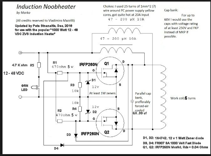
The unit I linked to earlier is a popular little induction heater on Amazon, Ebay and a host of other sites. These circuit designs are all pretty similar, The circuit for my link uses IRFP260N MOSFETs and the tank circuit is six 0.330 uF capacitors in parallel (about 2.0 uF) and the coil is about 2.0 uH Inductance. The end result is a resonant frequency of about 79.58 KHz. The coil is 6 turns of .250" copper tubing with a 2.0" diameter. The whole cartoon (my boss was an ME and called my schematics cartoons) looks like this:
Induction%20Heater%201%20KW.png


While all of this techy stuff can be interesting it likely makes very little sense to the guy who just wants to resize his brass and get good neck tension. I will add this. Circuits like this, designed for 12 Volts to say 48 Volts will not even start to oscillate at a voltage below 11 Volts. What happens is one MOSFET will start conducting, nothing will change state and it will die a horrible death. You want a power supply capable of at least 12 Volts and about 7 Amps to be on the safe side. Also, you never want to use a variable or adjustable supply and start with a voltage below 12 or 13 volts or bad things will happen. These circuits do work as off the boat from China but they are easily killed in a plum of smoke.

This concludes my little off topic contribution, we can now resume gun stuff. Electrical engineering types with a fetish for guns worry me. :)
</OffTopic>
 
Ok, granted we got off topic.

Unclenick: Can we get just an annealer group just for these twisted discussion?

For sure there are people wandering around with a glazed look and that is dangerous,

NOTE: Keep away from the reloading bench until you decompress!

It was back about 1982 I got into the electrical world, more generators and switchgear as well as starters and motors, not a huge need to get deep into some areas (or I had enough on my plate) .

So yes, it was E and I and R and then P when I needed to deal with generators and load banks and what was I pulling on that engine with a resistive load . Twinkle twinkle little star, E = I squared R. and all that.

My UPS systems (rectifier/dc link/inverter) did have all that but it was a Sams guide sort of troubleshoot , waveforms and voltage levels correct until they were wrong or gone and then it was back to the previous testing point. they don't even have testing points anymore.

We learned all that and then just changed out board (after we proved that was where the problem was)

Also power supplies are not my forte.

Now I know I am going off tangent, but if the power supply says 12 to 48 VDC, then should it not accommodate the 12?

I do have sensors that will take 12 to 32 or some such, AC or DC. Some like cheap voltage seniors just use a heavy resisters to drop the voltage to a lower level (and they fail after 10 year)

Transformers are more better but this is AC so you can do it with them.
 
...you are introducing an element of resistance in this that does not factor in.
Voltage can only be measured across resistance. If there is no resistance, there is a short circuit and the potential across a short circuit is always 0 volts.

Therefore, anytime one is dealing with non-zero voltage, there is resistance in the equation somewhere, even if it's not explicitly called out.
12 volts at 10 amps = 120 watts
24 volts at 10 amps = 240 watts.
True. However, if you're talking about the same circuit and there is no current limiting circuitry in there somewhere, increasing the voltage must also increase the current.

I = E/R

Increase voltage with resistance remaining the same (because it's the same circuit) and current must also go up linearly.

Since P = E * I, then we can substitute for I from the equation above.

P = E * E/R = (E^2)/R
Once the power supply has hit 100%, it can't pedal any faster.
The way you will know that it can't pedal any faster is that you won't be able to get any more voltage out of it. The E=I*R relationship is fixed. If you try to increase E and the supply can't put out enough current to maintain the relationship you won't get any increase in E.
...the only circuit that the formula actually works on is a purely resistive DC circuit.
It works on any circuit, it's just that you have to deal with impedance instead of just straight resistance in AC circuits.

It is true that there are devices which can alter their resistance to maintain a constant current output even when the voltage is varied. That's why there's the caveat that if there's current limiting circuitry things are slightly different. However, even in that case, you'll know when you get to the end of what the power supply can handle because the voltage won't adjust up any farther.
 
If the OP has the heater referenced in post #10 the description states:

12-48V low voltage power supply
Rated current:20A
Rated power:1000W, the bigger voltage, the higher power
This circuit can do induction heating, or replace copper tube with high frequency transformer, it will be a powerful inverter
The higher voltage, the higher current when heating the same things, the effect is better, but at the same time heating is also higher, therefore the choice of input voltage is based on your need

Note the third line and the last sentence.

Seems to indicate more voltage with sufficient amperage may solve his issue.
 
RRC20 said:
Frankly I think we have to disagree on this, you are introducing an element of resistance in this that does not factor in.

Putting it simply, I double the voltage, the power only goes up double, not squared.

We're talking very basic physics here. There really isn't any room for disagreement as there is with an opinion. Without resistance, current won't make heat, and this is a heater, so there is resistance. Your description suggests you are doing something that, in theory, only God can do, and that is violate Ohm's Law. I suspect, instead, you have a measuring error. They are really common with switched alternating currents. Standard DVOM's, including even the true RMS types, often can't handle some of the waveform crest factors involved. And even where the wave is a sinusoid, since AC power is EI times the cosine of the phase angle between voltage and current (a.k.a., power factor), if you don't have a means to determine power factor or don't add power factor correction capacitors between the power supply and load, you get wrong numbers.

I remember when the Newman free energy machines were a craze and conspiracy theorists claimed they were being suppressed. They appeared to provide free energy because the spiky waveforms off their contactor switches gave everyone's Radio Shack meters false high readings. Those meters couldn't accurately handle crest factors of over about 3 or 4. Even my Fluke only handles a crest factor of 7, while some spiky waveforms can have crest factors in the hundreds. When the Army investigated the claims for the device, that's what they found. No free energy, after all. Just electricity conventional meters couldn't read accurately.


The idea of a separate induction annealing forum is probably not going to fly here, as it's getting a bit off the beaten path and would be unlikely to be of interest to the majority of the BBS readers. So far, we are OK in the regular handloading forum as there aren't many of these threads. However, there are electronics forums out there that have threads about induction heaters. This one at 4HV.org, for example. Heating thin wall tubing may be a bit of a specialty, even there, but it seems less far afield.
 
As to heating brass I dragged a boat anchor power supply out of the shed with help of my neighbor. This sucker must weigh 100 Lbs or more, old linear 10 to 60 volt and 0 to 18 amp. I also dragged out a SainSmart 1000W ZVS Low voltage induction heating board module/Tesla coil 12V-48V and surprisingly the power supply and induction heater worked. Actually I was surprised the old power supply worked.

With 24 Volts applied the idle current was about 4 Amps. Placing a steel screwdriver in the coil the current rose as expected but only to about 8 amps. It will cook steel screwdrivers. To get it to draw 10 amps with 24 volts applied I had to shove a 1" diameter round steel rod in the coil. I used a steel dowel I use for lapping scope rings. I shoved a piece of 30-06 Springfield brass in the coil and while the current did increase with the brass load not much was happening. The brass did start to get hot but nowhere near what would be needed. I didn't instrument the brass but it was not all that hot, certainly not annealing temperature. As expected there is a big difference between the heating of brass and steel. The main difference is between the alloys, ferrous metals verse non-ferrous metals, the ferrous family being much more induction heating friendly.

While brass will heat and obviously can be annealed using induction heating it will take a little more refinement than what can be done with a $39 Amazon unit. Maybe tweaking the coil would help and getting a frequency change but out of the box? Good luck. :)

Ron
 
The current draw increase is due to the steel acting as a shorted secondary winding on a transformer, with the induction furnace coil being the primary. The thin brass doesn't intercept a lot of lines of induction from the primary, so it's harder to heat. The thickness relative to the wavelength of the oscillator frequency is also low. Higher frequency will work better.
 
I was aware of that Unclenick but really didn't see much sense in including it as only a few here would understand it. :) I just left it at Brass Vs. Steel but for those wanting to try one of these things verse an induction heating unit built for the cause save your money or learn induction heater mod 101 real quick. That was my point.

Ron
 
My take is the 1 inch coil listed is too big for the Brass, whether you can make it smaller without messing up the output of the power supply?

Again I don't claim to be an expert in this area, but I don't think the steel acts as a short.

More like a motor LRA (or a linear motor not moving - been there, done that a tech had to some form the East cost to fix that mother of all switches) .

And again my theory is not great but heat can be inducted in different ways (as well as power transfer)

This are more efficient ways to transferring heat, so I don't think pure adherence to the formulas describes what is going on in these circuits. They don't work for AC as they don't account for count EMF.

Or as I have always told the engineers, you can take your calculations and percentages of efficient, all I need is how many amps at how many volts its being pushed with and I can valuate heat accurately.

He needs more volts and or closer coil.
 
They don't work for AC as they don't account for count EMF.
They work just fine for AC as long as you understand that AC calculations must take impedance into account, not just straight resistance. Back EMF is a form of resistance/impedance, and it must also be taken into account when considering resistance/impedance for use in the Ohm's law calculation.
all I need is how many amps at how many volts its being pushed with and I can valuate heat accurately.
And you can figure the effective resistance as well--including things like EMF and impedance in AC circuits--if you know the current and potential.
 
Well I have some 0.250" copper tubing and a good 1" ID form so tomorrow I'll see what happens with a tighter ID coil and see how close I can get to the original coil's 2.0 uH inductance. Long as this creature is occupying the kitchen table anyway.

Ron
 
You can't get there from here in very good shape. If I assume 1/16" spacing between turns, the length per turn (5/16") means you'd need a 5½" long coil with about 17½ turns on it. So you wouldn't be able to insert the case into a very high percentage of the flux.

Do you have the single-layer solenoid formula?

Where the conductor is round in cross-section:

r is the mean radius (half the sum of the inside diameter and the conductor thickness) in inches

L is inductance in microhenries

N is the number of turns

d is the length of the coil in inches

L = (Nr)²/(9r+10d)

There are also on-line calculators. This one has you enter mean diameter instead of radius, so you'd use 1.25".

I think you want to look at a ferrite core or you want to use squashed tubing or a spiral of flat conductor. More complicated to do, but possible.
 
Unclenick:
You can't get there from here in very good shape. If I assume 1/16" spacing between turns, the length per turn (5/16") means you'd need a 5½" long coil with about 17½ turns on it. So you wouldn't be able to insert the case into a very high percentage of the flux.

Do you have the single-layer solenoid formula?

Where the conductor is round in cross-section:

r is the mean radius (half the sum of the inside diameter and the conductor thickness) in inches

L is inductance in microhenries

N is the number of turns

d is the length of the coil in inches

L = (Nr)²/(9r+10d)

There are also on-line calculators. This one has you enter mean diameter instead of radius, so you'd use 1.25".

I think you want to look at a ferrite core or you want to use squashed tubing or a spiral of flat conductor. More complicated to do, but possible.

Which is why a blow torch is beginning to look better and better. The same blow torch which got it done for decades. :) Maybe I won't waste the tubing. I already had to get my neighbor help me get my boat anchor power supply up on the table, which reminds me I still have to get that thing back down and before she who must be obeyed gets too mad.

Ron
 
I told her to think of things right now as a transitional state. The gun room is moving and also the new area will have a small electrical electronic workbench. :) Yes, she has been very patient with me, actually for a very long time.

Ron
 
Well, the electrical engineer advanced lessons in theroy drove the OP to PM me...

1. Running the unit at less than 1/4 of it's potential at 12vdc @ 850A.
Need larger power supply.

2. All the electrical theroy in the world isn't going to tell you that a HSS drill is highly ferrous,
While your brass cases are very low on the ferrous scale.
The steel drill works to focus the magnetic field, the drill is the center core,
While a hollow brass case (80+ percent copper) is both highly conductive, and most ferrous scales will call it 'Non-Magnetic'.

ANY electrical conductor MUST be slightly ferrous, even if it's 'Common' to call it 'Non-Magnetic'
Even water can be attracted or repelled by a magnetic field, and as many can tell you, the induction units often move the case during annealing...

3. When cases move, and being highly conductive, they WILL short out the annealing coil, further reducing the effectiveness of the annealing unit.
Use a high temprature electrical insulator on the winding, something like a woven fiberglass wrap on the windings.
Doesn't have to be an arc insulator since at such high frequency it's very unlikely there will be enough time for the air to ionize and an arc to form.
You just need a few fractions of an inch between brass and coil windings.

4. Since the brass can't work as a magnetic focus (too low on the ferrous scale),
And since the brass case is too high on the electrical conductivity scale to provide an induced electrical resistance, (both in play with heating the drill),
You should probably consider a ferrous core, like a 'C' shaped Ferrite ring.

There are 'C' shaped Ferrite cores available, but finding the exact right one is difficult on the surplus market, and something specific from a manufacturer will run you in excess of $100,
I suggest you check eBay for surplus 'O' or ring Ferrites ($3-$10), and buy a carbide abrasive jigsaw blade ($5) and make a 'C' out of an 'O'.

I've had great success by shaping the gap to fit the specific case necks/shoulders simply using a ceramic tile cutting (abrasive) blade in an angle grinder and/or Dremel tool.

5. Ferrite & STRANDED WIRE!
(This is where the EE types blow a fuse and loose their minds!)

Stranded wire does, and will, out perform solid wire in this application.
All the electrical engineer types blow up at the mere mention of this, but you are looking at knocking a second or two off the time simply by switching from solid to stranded wire coils with a Ferrite.
This is NOT theroy, this is direct observation of a dozen or more of these low powered units.

The theroy is, with this high of frequency, the current acts more like AC instead of DC.
AC has something called 'Skin Effect' or 'Surface Effect' where current runs along the skin of the conductor instead of all through the conductor like DC does.
More strands means more 'Skin' or surface, and that produces more effect at the coil/case.

Since I don't have a full on electronics research lab, but that's the working theroy to explain what happens in direct observation, provable results.

6. If you are still way off...
This one won't do you any good, but if you get 'Close', this might put you over the top.
Litz Wire.

Litz Wire is many strands, all insulated, inside a common insulating layer.
It's used in a lot of very high frequency applications, like radio frequency applications.
When you strip each conductor, solder the ends together (use silver bearing electrical solder) they make a reasonable contact point.
This will squeeze the last few electrons out of your windings, slightly increasing effectiveness, measured by reduced heating time.

On the lower powered units, it sometimes puts me over the top on temp at reasonable time, but be advised, used only with a Ferrite and used only when the units is switched On/Off (short duty cycle) so the winding has time to cool between cases.
If you get Litz Wire too hot you will smoke the insulation...
Since you are switched, this could be the last 5% once you are very close.

I switched to Litz wire/Ferrite on a 48vdc/1,500W power supply and burned the necks off cases at the same time a sold wire coil was not getting the case to temp in a reasonable time.
You might want to use not so good cases in the beginning or sneak your timer up if you make this change all at once.
I'm not talking overheating the necks, I'm talking REMOVED the necks from the case body in under 15 seconds.
The heating time dropped from 15-18 seconds to 3.2 seconds on .223 brass.
15 seconds simply removed the necks changing nothing more than from solid coil to 'C' Ferrite with Litz Wire.
 
Status
Not open for further replies.
Back
Top