Calling all electrical experts induction help

Status
Not open for further replies.
I have dyi induction annealer that I constructed using a 1000watt induction board off amazon work with 12-48 v lots dc currently using a 12.7 825 watt power supply I have replaced the coil with #8 solid copper wire and made the diameter approx 1” inside. The issues I’m having is it will bring a drill bit 1/4” to 1200 degrees in 18 sec but I’m unable to reach the 725-750 degree mark on a piece of 6.5 hornady brass it gets to approx 380 using a thermal camera. This is in a 2 min time. What are some suggestions or fixes that I could try. Thanks in advance
 
Induction heating works better on ferrous metals than on non-ferrous metals and better on poorer conductors than on good conductors.
 
I understand that induction works on an substance that is more ferrous but 1000s of piecesof brass are inductioned annealed everyday so it is possible. So I’m asking those that have constructed these diy’s for input on how to fix what I have
 
I have not built such a device, but the solution would appear to be "more power". I found one induction brass heater designed for your application and it was running at 1200 watts; about 50% more power than the spec for the power supply you're using.
 
I'm not very familiar with induction heaters, but I believe the one you have won't produce rated power at 12V. You may need to increase the input voltage to 24V or more to get the power (heat) you need.
 
Last edited:
You might try using a 12 volt car battery as a power supply. That will give you all the amps you need. If that works, you need a bigger ac power supply. If it does not, you need more voltage such as a 24 volt supply rated at 1200 watts or so. Just be sure that you use big wire to connect with the auto battery.

Edit: The above assumes that your 1000 watt induction board will actually put out that power; made in China you never know. Also I'm assuming you have verified that 1000 watts is adequate for an induction anneal machine since I have no direct experience with them.

Edit #2: Here's an off the wall suggestion since you are experimenting. Maybe your induction coil would benefit by using Litz wire https://en.wikipedia.org/wiki/Litz_wire. Note that it is used in induction heating to alleviate the "skin effect" of normal wire at low frequencies. Read the first paragraph in the "How Litz wire works" section and note the tubing reference. Since the wire is hard to find and fairly expensive and also a PIA to strip, I'd go to Home Depot or Lowes and buy a foot of 1/8 inch copper tubing and wind the coil out of that. Have no idea if that would work (I still suspect you need more voltage/power), but it would be a cheap and fun experiment.
 
Last edited:
Maybe Jeephamer will weight in, but 1 inch diameter?

The coils needs to be fairly close fitting, not tight, but more like 1/2 diameter.

It also depends on if the power is stepped down to a nominal voltage (12) or you are only getting 250 Watts.

My Annie is 1200 watts so power if you are getting it is in the ballpark.

But coil closeness, turns and the wire type all play a factor in this.

I work a lot of electronics but designing is not my forte, I fix em, the theory gets too far out for me.
 
You likely have a SainSmart 1000W ZVS Low voltage induction heating board module/Tesla coil 12V-48V or similar from Amazon. I will tell you what your problem likely is. You are driving the board with a 12.7 Volt 825 Watt power supply or roughly a 12 volt supply capable of delivering about 65 Amps.

The problem is in how these boards actually work. The board is capable of about 1 KW but you will only get that with the maximum DC Voltage of 48 VDC applied. With 48 VDC applied the board will draw right around 20.8 Amps of current so we get 20.8 Amps * 48 Volts = 998.4 or roughly 1,000 Watts (1.0 KW). With 12 VDC applied that board will only draw about 5 Amps or roughly 1/4 the current it would draw at 48 Volts applied. The fact that your power supply can supply more current at 12 Volts really matters not. Your actual power with your configuration is about 250 Watts.

Connecting the unit to a car battery won't make any difference. While your existing 12 VDC supply is capable of about 825 / 12.7 = 64.9 Amps the induction heater board will only draw about 5 Amps with 12 Volts applied. I do not recommend changing the coil and the reasoning is that the unit was designed to operate at a given frequency with a coil having the Inductance it shipped with. You can get by with minor changes but I seriously doubt you will get the results you want making changes to the coil. The little black gizmo parts mounted to the aluminum heat sinks are MOSFET devices and if you start changing things they won't oscillate and there is a possibility they will become suicidal (bad things happen).

Your best bet is increase the Voltage and as mentioned when doing so make sure you use wire which will handle the current. Going to a 24 Volt supply that board will draw about 10 Amps and allowing a margin I would use AWG 14 wire.

Ron
 
Reloadron said:
With 12 VDC applied that board will only draw about 5 Amps or roughly 1/4 the current it would draw at 48 Volts applied. The fact that your power supply can supply more current at 12 Volts really matters not. Your actual power with your configuration is about 250 Watts.

12V × 5A is 60W. Power goes up as the square of applied voltage because the current is also increasing with it. The power numbers, however, assume 100% efficient coupling of the potential power to the load, which seldom happens. So it will be less than 60W actually at the brass.
 
I am going to disagree Formula is E x I = P :confused:

If you double the voltage the power goes up to 120 Watts (24 x 5)

Power consumed is not necessarily power delivered but the voltage current relationship is linear.
 
Last edited:
I ran the numbers, it would take 21 amps with 48 volts (rounded) to get 1000 watts out of that power supply and that assumes it goes to the coil with no loses (can't happen)

That is matches Reloadron input (pun)

However, he needs 40 amps at 24 to get the 1000 - otherwise at 10 amps he gets at most 240.

Your best bet is increase the Voltage and as mentioned when doing so make sure you use wire which will handle the current. Going to a 24 Volt supply that board will draw about 10 Amps and allowing a margin I would use AWG 14 wire.
 
RC20 said:
I am going to disagree Formula is E x I.

If you double the voltage the power goes up to 120 Watts (24 x 5)

How are you going to double the voltage from 12V to 24V without raising the current from the 5A that it had at 12V?

Ohm's law: E = IR

To double E, you obviously have to at least double either I or R or use a combination of increases in the two that doubles E. The R will go up a bit as the brass heats further, but it won't heat further if the current moving in it remains the same. So raising the voltage will raise the current. If the load resistance remains constant, the current will double, so you will go from 12V×5A to 24V×10A. Power will then go from 60W to 240W, or an increase of a factor of 4. Since we changed the voltage times 2 and 4 is the square of two, the power has gone up as the square of the increase in voltage.

P = EI = E²/R

The above is true because, by Ohm's law, I = E/R and if you substitute that for I in the first form of the equation, you get EE/R or E²/R.

In reality, the load resistance will not constant with heat, and you'd need a differential equation to find where the voltage and current actually reach equilibrium, but it will be at more than double the power. The real complication is we don't know how much power is lost in the coil resistance nor how much of the current is through reactive impedance instead of resistance. The actual power dissipated (or delivered) by an alternating current, unless you have a perfectly resistive load, is always complicated by the fact reactance (AC impedance due to inductance or capacitance) doesn't dissipate power; it merely goes into storing energy or comes from taking it back out of storage again. Since reactive current and resistive current are 90° out of phase with one another, the power dissipated by AC is:

P = EI cos(Φ)

Where Φ (phi) is the resultant phase angle from the combination of resistive and reactive currents. We don't really have a handle on that in these induction heaters without making some measurements, so we can't easily guess how much power is actually delivered to the case. We just know what the heaters claim to be capable of delivering to an ideal load.
 
Unclenick:

That is where this all get tricky.

Think of it as a fuel line. Assume the pressure is 12 psi and the line is partially blocked. Fuel flow is 5 gallon (minute). You only get 60 hp.

Make it 24 psi and you double it to 10 gpm, you get 240 hp (still too little for your supersonic car but better)

In other words its a dance. If you want to do 1000 mph, you need the power.

If you have a board that can work from 12 to 48 volts, it has to have the 48 volts to move the amps to do the 1000 watt work.

Now, its not always that simple in a electrical circuit, lots of factors can play in.

You can't make more watts than the power allows.

The board is starved for potential.

Yes it could do 1000 watts with 12 volts, it needs to move 83 amps to do that.

Heavier wires, components etc. More better to do it with 48 volts and 21 amps.

Its all a dance.
 
RC20 said:
I am going to disagree Formula is E x I.

Well, now you leave me to wonder what you were disagreeing with? We're saying the same thing. Increase the voltage to increase the current. That will drive the power up as the square of the voltage increase if the load resistance remains constant.

As to what limits the input current at the lower voltage, that's mainly going to be the coupling coefficient between the tank circuit coil and the load. Reducing the power feed resistance or the coil resistance or even going to bigger MOSFETs with lower RDS(ON) ratings, probably won't do much.

I've been an electrical engineer and circuit designer since the mid-1970's, so if I have any of this wrong, I am in far deeper doo-doo than a mistaken Internet post amounts to.
 
You are saying square and I am saying its linear darn it!


12 volts at 10 amps = 120 watts
24 volts at 10 amps = 240 watts.

double voltage does not square the power

if it was capable of changing the amps (power supply can do that if its setup to work that way - it just has to be robust enough.

12 x 10 = 120

12 x 20 + 240.

A way to do that is variant resistance, lot of waste head though, brute forced thing best left for small drops. That is a square function but lots better ways do it.
 
Yep. Exactly. You can't increase the voltage without increasing the current into machine. If the power supply is a current limiting type with a 5A limit, you could set it to 24V, but as soon as you powered the unit up, it would drop its output voltage back down to 12V, because that is what it would have to do to keep the current limited to 5A. You can't have both higher voltage and the same current unless the load itself is a constant current drain, and these very simple, inexpensive induction heater circuits are not such circuits.

P=EI

Ohm's Law in its three forms:

E=IR

I=E/R

R=E/I

Suppose you have regulated power whose current limit exceeds anything drawn in this example:

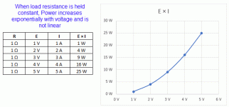
You apply 1V to a resistance 1Ω. Ohm's Law in the second form above says:

I = E/R = 1V/1Ω = 1A

Power dissipated in the load is then:

P = EI = 1V×1A = 1W


You apply 2V to the same load, a resistance of 1Ω.

I = E/R = 2V/1Ω = 2A

Power dissipated in the load is then:

P = EI = 2V×2A = 4W


You apply 3V to the same load, a resistance of 1Ω:

I = E/R = 3V/1Ω = 3A

Power dissipated in the load is then:

P = EI = 3V×3A = 9W.

attachment.php


So, as you increase voltage while keeping the load at a fixed resistance, the power goes up as the square of the change in voltage. That is not linear because power is the product of two factors that are going up at the same time, the same as a square is. Change in power would only be linear if you could increase the resistance in the circuit in proportion to the change in voltage, making one factor that increases power go up while another that decreases power goes up at the same time.

For example: Suppose we go through the same numbers, but with resistance increasing with voltage.

You apply 1V to a resistance 1Ω. Ohm's Law in the second form above says:

I = E/R = 1V/1Ω = 1A

Power dissipated in the load is then:

P = EI = 1V×1A = 1W


You apply 2V to a resistance of 2Ω.

I = E/R = 2V/2Ω = 1A

Power dissipated in the load is then:

P = EI = 2V×1A = 2W


You apply 3V to a resistance of 3Ω:

I = E/R = 3V/3Ω = 1A

Power dissipated in the load is then:

P = EI = 3V×1A = 3W.

You can see we had to increase the resistance of the load to hold the current down to its original value of 1A in order for power to go up directly (a linearl form) with voltage. But there in nothing in an induction heater load to make the resistance go up like that. When the resistance does not go up, use the second form of the power equation to avoid confusion:

P = E²/R

Again, this just substitutes the right side of the second form of Ohm's Law for I in the other form:

P = E×I = E×E/R = E²/R
 

Attachments

  • EI Plot.gif
    EI Plot.gif
    13.2 KB · Views: 439
Status
Not open for further replies.
Back
Top