How To Remove Firing Pin Frame Mounted S&W Revolver

To

Jim Keenan


Hi;
I am syamsunder a junior member.
Here is your previous text

One reason for the confusion here is that S&W has changed the design of that frame mounted firing pin. In the new design, there is no firing pin bushing. The firing pin comes out to the rear and is held by a slip fit pin that is just pulled out when the side plate is removed. A lot simpler and less costly to make.

Does it mean that in new design a bore is made in to breech plate of diameter to suit F.P base and spring' with concentric small diameter hole ( i think between 1.8 to 2 mm dia ) for F.P small diameter part

Then support given on back by slip fit pin ?

In the photo of F.P of s& w there is a slot visible on base part ( large diameter part ) .is it new design or old design ?

what is the utility of that slot ? Any pin is introduced in to it from side direction from frame that provide sliding as well as retainer function ?
Please draw a hand diagram of the system using windows paint and post.

can you mesure dia (outer )of bushing and let me know ?

thanking you
 
I made an error in what I said. I meant to say there is no firing pin bushing pin. There is a firing pin bushing, but it does not need to be removed to remove the firing pin and spring, like it did on the old K-22.

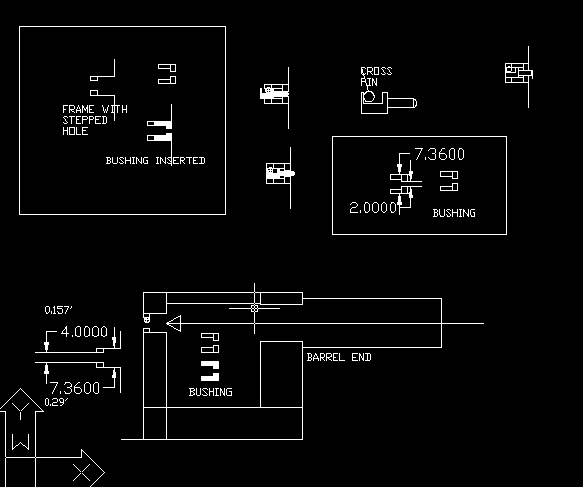
A stepped diameter hole is drilled in from the front; the front part is about .29" and holds the bushing. Rear part is about .157". The bushing is put into the front in the normal manner, then appears to be swaged in to retain it. The firing pin is like the one shown, with a half-moon cut for the cross pin that retains it. The cross pin is a slip fit in the frame and is not visible until the sideplate is removed. Then the cross pin can be removed by simply grasping it with small pliers, and pulling it straight out, at which point the firing pin and spring can come out.

It is a pretty simple setup, and does away with the hammer nose and its retainer pin, eliminating a tricky assembly step (and the associated cost), plus some internal frame machining to direct the hammer nose.. There have been some problems with breaking firing pins (the subject of this thread), but I have no doubt that will be resolved.

Jim
 
ScreenHunter_03May290246.gif


Thank you sir for your kind reply

please see this line diagram and coment if i understood your reply properly or not.

one image is worth thousend words

previously i thought that a through and through hole is made in to breech plate of diameter of bushing.


with the steeped hole there will be support to back of bushing ; from that coller formed.
Am i correct ?

ScreenHunter_04May290314.gif

here is another simple idea -threded houseing
please coment
 
Last edited:
threaded bushing

here is another simple idea -threded houseing

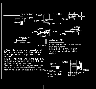
here there is a coller to threaded bushing through which a 3 mm cross pin is passed to give similar function to firing pin
The tip of M-3 bolt can be smoothened to 2 mm ofcourse.
I have added a 8 mm coller to firing pin itself ( there is no insertion problem being an open configaration) this increase area of contact so F.P can face battering from hammer better.
M-6 or m-7 threading can be laid from back side in to breech plate by a tap with extralength of stem attached.
M-7 *1.0 is also an avilable tapset sige.
you have mentioned dia of bushing as 0.29 inch =7.36 mm
This model however occupy 6.5 mm height.
 
This is the image of my thought

ScreenHunter_03May310300.gif
The S&w with lot of establishment & expertise can go for c.n.c product.
I do accept the elegent design of it with Bushing mounted from barrel side which doesent need removel.
Now i have a little doubt. when it is functionally fixed entity it is functioning as stopper to spring & firing pin nose .Only force that pushes it outwards is spring tension probably counteracted by close grinding of its outer dia to match the 1st step in bore of frame ;;; much similar to bearing fitting of general enge works.
ok.
The same front stoper function can be achived by making concentric two stepped hole from behind also ; insted of from barrel side; here the frame metal itself make said stoper function.
there should be some practical need to adopt this round about route.
The bushing can be hardended to a higher degree to tolerate hitting from recoil of catridge & primer cup.

Am i correct ? any other reason ?
i also doubt it may be practically difficult make very small dia drill ( 1.8 to 2 mm dia ) at lot of depth on to breech plate to suite dia of firing pin directly.
same can be done easily on to a separate Bushing . Is it the reason ?

Here is the diagram of my proposed Firing pin Houseing with in a threded insert.
Here Firing pin is similarly haveing a step in its base to receive the tip of M-3 bolt which is passed from coller of that threded houseing.
That coller can be provided with a parting slot on its face for tightneing purposes.
This firing pin shape is very similar to S&w without any coller ; not as in my previous diagram posted.
This arrangement takes 5 mm height from breech plate 3 mm for m-3 bolt 1 mm on either side as metal margin.
Did any body in past prepared such arrangement ?
 
Last edited:
It might be possible to drill out the firing pin hole from the rear on the hammer guns, but exactly how would one do that on the concealed hammer guns? Drilling from the front also keeps the bushing and firing pin hole concentric with the barrel and is just plain easier.

Threaded bushings are common on break-open shotguns, but require a special tool for removal. Plus there would be additional machine operations to thread the bushing, thread the hole, and drill the disassembly holes, with a fairly large increase in costs and with no discernable advantage. IMHO, the new S&W system is much better.

Remember, it is easy to put stuff on paper or in a CAD program, but a factory engineer has to make something that can actually be produced at a reasonable cost and can be serviced.

Jim
 
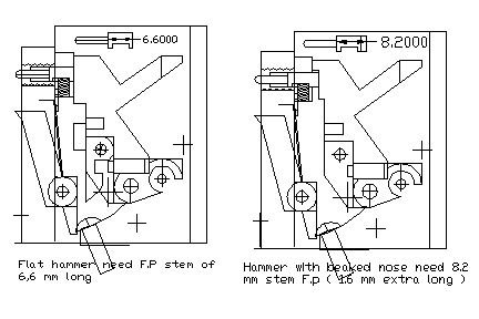
nose shape of hammer

what are the factors that affect nose shape of hammer.
These are the following nose shapes for frame mounted firing pin

1* Flat face
2* flat face with a beck ( a step in vertical direction )

3 Flat face with a verical slot of width a little more than firing pin diameter.

which of them is best ?

Regarding hammer mounted firing pin --- is the diameter of firing pin is same as that of frame mounted firing pin.
 
I perfectly agree with you

i perfectly agree with you . what all possible on paper is not possible practically.

But what is not possible on paper / thought can nerver be possible practically leaving alone singularities of nature like in certain situations of quantum physics. ( like possible simultanious double existance and parrelel world theories )

Always i see a anology / patteren in predicting gap between thought and practice is like sequencial logical filters.

in dreems we can simply fly defying gravity. but in reality we can't. The gap between thought and external reality is because there is no absolute inner limitation ; but as we start simulating more and more external natures rules in our inner wold ;;more and more closer our imagination to external reality.

But at each stage of adding one more rule the picture changes.

like example here there is natures rules like a thin metal section behaves differently to heat treatment .That fact may not come to mind in initial design.
----------------------------------------------------------------
sir ; when C.N.C machine is at your hand then one process may be easier/ economical.
But when when you are with simple old day machines / lathes tapsets/ files ect with lot of manpower and no problem with time some other process may be cheeper.
so what i am here asking you is ( leave alone cost considerations ) if threaded houseing is having any other FUNCTIONAL PROBLEMS comapared to more advaced model of S&w ?
 
Please do not take this wrong, but I have to say that you sound like a college sophomore. (How would I know? Been there. I sounded, I'm sure, just like you.)

FWIW, man's inability to fly like a bird is not related to any lack of imagination, but to purely physical factors, like bone mass and muscle strength.

No, there is no reason not to use a threaded bushing any of your designs would work; as I said, it is common on double shotguns. The bushing is made with two little side holes so it can be removed with a special tool. Inserting the bushing from the rear, though presents other problems, like how do you drill and tap the frame on a concealed hammer gun?

I wonder how much experience you have with CNC machines. They are not magic; any machine operation requires money spent on the machines, the tools, the power and the operator, plus the time and cost of the operation itself. Then the assembler has to screw in the bushing, another time consuming operation. All of that is a lot more costly in time and labor than simply pressing in a bushing and using a swage, all in one pass. In your second design, you introduce another production problem, with another threaded hole and screw to hold in the firing pin. More machine operations, more time, more cost, more difficulty for the gunsmith who has to replace something.

Your design thinking is OK in countries where labor and tools are cheap, and the 10 or 15 seconds to screw in a bushing won't mean much. But designers today, in a competitive environment, don't have the luxury of "cost is no object" that prevailed in older times. A designer or a production engineer of a consumer product who can save ten cents in costs or two minutes of production time is a hero.

There is absolutely nothing wrong with your design, but it is costly and has no advantage. You are falling into a common design trap - starting out to simplify something, and ending up with an even more complex system.

As to the hammer shape, the cutaway hammer face itself has no advantage; it is done for another reason, usually to allow use of a transfer bar system, which S&W does not use.

Jim
 
Thak you sir for elaborate reply.
i agree the beauty /elegance of s&w design. It is also true that the design i made is much more complex .may be with out much benefit.
--------------------------------------------------------------

I also heard a saying KISS concept ( keep it simple stupid ) where a astronaught tried to make highly complex barometric based pen for space applications ; in ink pen days. ( in space ink pen wont work )Then one of his friends suggested that using pencil is a good alternative. This is an example of KISS concept.

--------------------------------------------------------------

I am left with one doubt.
the recoil force on cartridge and primer is going to push back the firing pin is well known fact.
The area of cross section is small to resist this force by a small pin against a mini step may be 1.5 to 2 mm deep inside base of firing pin ( firing pin base dia = 4 mm nearly )
The cross pin itself is nearly 2.26 mm dia it seems to me when i have taken a tracing on over the photos you have provided.
i wonder how such small stopping surface is working.
I do not deny it is truly working .
(The older frame mounted f.p designs are with a separate recoil plate.
there the f.pin has a collar of about 7 mm dia in front of 4 mm dia zone .)
 
The primer does indeed push back on the firing pin, but the firing pin is backed up by the hammer, which in turn is backed up by the mainspring. So the firing pin never actually moves backward in firing and the situation you envision does not occur.

Even in guns with inertia firing pins, like the M1911 pistol, the momentum of the firing pin is sufficient to prevent the primer metal from being forced into the firing pin hole (the so called "pierced primer"). Quite a few people, including some who should darn well know better, think a "pierced primer" is due to a sharp firing pin or too hard a FP blow. In fact, it is due to primer metal being forced backward into the firing pin hole, the result of a too soft firing pin strike.

Jim
 
1**can i understan that strong hammer main spring is better than week one in preventing peirceing of primers ? so that primer cup will not enter the F.Pin hole ?

2** Is the firing pin dia ( at tip ) of hammer mounted firing pin is same / nearly same as that of frame mounted firing pin ?

I know that tip dia of Frame mounted F.Pin diameter = 1.8 mm to 2 mm .

I am not aware of similar figure of hammer mounted Firing pins .

kindly clarify .
If it is also nearly 1.8 to 2 mm then it needs very narow sloat of 2 mm width need to be made in to breech plate for passage of hammer mounter F.Pin .

I am surprised hoe in olden days of hammer mounted firing pins they are able to make such narrow slot in to breech plate.
 
Back
Top