H&R Self Loader

timgd

New member
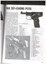
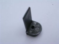
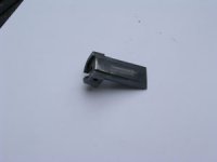
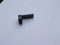
Bought a .32H&R auto pistol at a lgs a few months ago. It seemed to check out ok at the counter, got it home field striped and lubed, every thing looked good I put it in the safe. Took it to the range this weekend it didn't want to accept a loaded mag. Once I got the mag seated the slide wouldn't go into battery. Striped the slide and found the catch hole in the slide end plate all buggered up and the pin that holds the block and ejecter in the slide was broken and not holding 1 side of the block in place, its all messed up and might need replacing .I don't really know what it looks like and haven't been able to find a picture of it too compare it with. Does any body have a schematic or picture they can send me or know where i can find the information I need. If I can't find a new part I can make one if I have too.
Thanks Tim
 
Can you post a photo of the damaged areas? I'm not sure if my part nomenclature and yours will match.

Most certainly a broken pin will need removed and replaced. Numrich has some parts for these, but not all, and no schematic. A pin can be made from a piece of spring wire the correct diameter, if none is available. If it is the takedown detent, at the rear of the slide, you'll have to buy that is it's broke, or borrow another gun, and use that detent to have one machined like it.

These are a striker fired semi-auto pistols if I recall, (no hammer), and the original .25 cal. design was from Webley, however I'd say H&R modified a few things between calibers, since I think the .25 was hammer fired.

Parts at Numrich:

https://www.gunpartscorp.com/Manufacturers/HarringtonRichardson-33274/AutoPistols-36447/SelfLoadPistol-34980.htm
 
For those who may not know, the breechblock on the H&R is not part of the slide; it is a separate part, locked in by a shoulder and pinned with a cross pin. This was not done, as might be supposed, to make machining easier, but because Browning had patented a one-piece slide and breechblock, and H&R had to get around that patent.

To answer the question, the pin is 0.075"-0.080" in diameter and 0.82" long, with rounded ends. It is a drive fit, driven in from the left side.

It does not need to be especially strong or heat treated as it takes no strain. Its job is simply to keep the breechblock from coming loose.

HTH

Jim
 
The damaged part is what Jim is calling the breech block and here is damage to the sections that fit into the slide which seems undamaged. What I'm concerned about is on the back side of the block across the bottom it looks like some sort of tab .100 thk. has been broken off and lost this is the section I need to see. I'm a retired machinist with a shop in the garage and I will make the parts once I know what they look like.I have checked Numrich but wasn't sure of their nomenclature and didn't want to order until I knew what I was talking about.
Thanks Tim
 
If you can post a couple of pictures, maybe I can see what is missing. That "tail" forms the part that rides on the hammer when the gun is being cocked (think the bottom of the firing pin tunnel on a 1911). I can tell you that the "tail" is 1.11" from the face of the breech, and .50" wide. It is not the same thickness all the way; the front is about .072" the rear is ,057" The center is a ramp. The darned thing is intricate as heck; the cut for the extractor alone is pretty tricky.

Tomorrow, I will try to get pictures, but I will warn that making that part will not be easy without the tooling the factory had.

Jim

P.S. I earlier called that part the breechblock, but it really is a combination of the breech face and what would normally be part of the slide. I can't find any original parts list or diagram and also found Numrich's names confusing (there is no illustration).

JK
 
I will try to get pictures tomorrow. thanks for those numbers they are enough for me to at least start thinking about how to do my set ups. For what its worth from the machining and heat treat I think this part was a 1off from a gun smith the quality does not match the rest of the pistol.
Tim
 
I'm wondering if this part is what Numrich calls a bolt face [out of stock] if it is I might have found another one from another vender. I will call tomorrow and see if I can get a description of the used part they have.
Tim
 
Check the NRA Firearms Assembly handbook. Nice exploded drawing there.

Edit: Reduced the bytes. Here you go:
 

Attachments

  • H&R Self Loader Schematic.jpg
    H&R Self Loader Schematic.jpg
    210.8 KB · Views: 29
Last edited:
The correct name for what I had been calling the breechblock seems to be the "bolt face", so that is the term I will use from here on.

I am working on pictures now and will post a couple in a little while.

Jim
 
gyvel
Thanks for the link that is the 1st picture of the internal parts I have seen.
Jim
After seeing the schematic I agree that is not going to be an easy part to fabricate. I am going to give Hoosier a call right now. I hope they have the part since they don't seem to keep their site up to date.
 
You have to use a picture editor to downsize the photos, or downsize them with the camera. I hope these come through. Maybe they are too small but if you can't enlarge, I will send them bigger.

Jim
 

Attachments

  • DSCN3175.JPG
    DSCN3175.JPG
    30.8 KB · Views: 18
  • DSCN3178.JPG
    DSCN3178.JPG
    30.3 KB · Views: 15
  • DSCN3179.JPG
    DSCN3179.JPG
    29.4 KB · Views: 14
Jim
Your pictures will work just fine I do have 2 questions. 1-is the1.1 in. dem. from the face that the cartrige contacts or the surrounding lip? 2- how far out on the tab does the ramp go? Or how far from the end does it stop?
Tim
 
1. The 1.11" is from the face of the breech below the firing pin hole, not from the raised lip around the face. 2. The ramp goes all the way to the end, going from about .035" at the front to about .005 at the rear. There is a very slight lip (about .001") at the bottom of the breech face below the firing pin hole, but how much effect it has on case retention I don't know. It appears to be the result of the machining process, not intentional design.

There is no separate ejector; the firing pin serves as the ejector.

Good luck.

Jim
 
I'll add this. If I were going to try and make that part, and I had the actual bolt face (the "bottom of the L, with the extractor cut and firing pin hole and all) I would consider putting on the "tail" by dovetailing the bottom of the bolt face, then making the "tail" as a separate part to be slotted into the bolt face, then drilled so it would be held in place by the retainer pin. That would save an awful lot of close work and that "tail" does not appear to be under much strain.

Jim
 
Thanks for the clarification and just for your information I have already been thinking about how I could use the existing part and build up a new tab. Once I get going I will post pictures of what ever I come up with.
Thanks again for your time & help.
Tim
 
One small tip that I just recalled from years ago. The endplate detent is a little two diameter pin that locks the endplate in place. It is backed by a small spring. Once when I was assembling one of those, the detent took off for parts unknown and I had to make a new one (no big deal, but a bit of a PITA at quitting time). The boss gave me a tip, telling me that the small end does not go the rear and into the endplate (as I had had it) but in front where it went into the spring and the spring was crimped around it. The other end of the spring was spread so it stayed in the hole. In other words, H&R had made sure the detent, spring, and slide stayed together unless deliberately taken apart. (Browning used the same system with the safety/slide stop spring and plungers in the 1911.)

The larger part of the detent goes into the endplate (take a look at the endplate) and locks it in place.

Jim
 
timgd: Although I sort of hate to bring this up, you are probably better off finding an incomplete junker and getting the part from it. (I would imagine it's going to be a lot cheaper than trying to find that part for sale; You could then resell the parts you didn't use.)

However, if, as you say, you are an accomplished machinist, your best bet is to find someone who will loan you the part to copy.:)
 
Finding parts won't be easy if GPC doesn't have them. H&R only made about 31,000 of them, a pretty small production figure, and they were never popular.

I am reluctant to loan what could well be an irreplaceable part, though I will provide more pictures and suggestions if the OP needs or wants them.

I think the dovetail idea would work OK, and is what I would try; I will give more details or a sketch of what I have in mind on request. I think welding a piece on would be very iffy unless the welder were very skilled in micro work. A silver solder arrangement might work OK, as might using small screws.

Jim
 
I retired from one of the D.O.E.'s top national labs. I know and have access to some of the most talented welders in the country if not the world. I was leaning towards a welded fix rather than a mechanical one. Jim I am open to any type of fix so any sketches and pictures will be appreciated.
Tim
 
Back
Top