You are using an out of date browser. It may not display this or other websites correctly.
You should upgrade or use an alternative browser.
You should upgrade or use an alternative browser.
rear sight H&R 939 Old Revolver
- Thread starter w2kbr
- Start date


OK...so I just jumped into the removal of the rear sight parts...
Got it all dis-assembled with no problems.....
Planning to take some pix and include a few words, as I had no idea where all the parts were located on the piece, the plungers, springs, etc etc...
Maybe next time it will be easier for somebody else.......
Regards,
R
Got it all dis-assembled with no problems.....
Planning to take some pix and include a few words, as I had no idea where all the parts were located on the piece, the plungers, springs, etc etc...
Maybe next time it will be easier for somebody else.......
Regards,
R
")
H&R Sight (continued)
If I get the pix to upload, you may be able to follow this OK
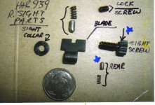
The first pix is the Rear Sight parts.
Upper center is the sight plunger and spring. The plunger is
machined to a blunt taper at one end, flat on the other.
Upper right is the lock screw found on the right side of the frame
adjacent to the Sight Screw.
In the center is the sight Blade showing the side you would see
if sighting the piece. To the left is the collar, and to the right
is the sight screw.
Lower right is the Elevation spring and plunger.
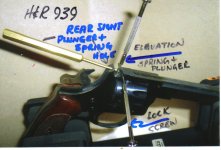
The second Pix is the piece in my gun vice, and I have inserted
tools in the holes in the frame. The bronze colored drift pin punch
is in the Sight Plunger and spring hole, It is home for the
beveled Plunger that rides against the serrations on the forward
side of the sight blade.
The top driver is sitting in the Elevation hole.The lower driver
is in the Lock Screw hole.
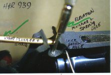
The 3rd pix is a closeup of the above explanation.
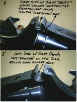
Pix 4&5 show close ups of the right and left side ofthe Sight"cavity"
NOTE the shoulders on both sides. Also the plunger holes and
the Lock Screw hole can be readily seen.
The "shoulders" on both sides limit the Collar on the Left side,
and the Sight Screw on the right side. Note that the sight blade
is "offset" relative to its' "threaded barrel" below the blade.
The offset accomodates the difference in thickness of the Collar
as opposed to the thickness of the sight screw.
The distance between the two shoulders is greaterthen the thickness
of the "threaded barrel" of the sight blade.
By manipulating the blade on the sight screw threaded shaft, the sight
blade can be set "Left" of center, or "right" of center, thereby
allowing a bit on "windage" adjustment.
And interesting exercise is to thread the blade onto the sight screw,
then add the collar,, and with both Plungers still out of the "Cavity"
insert the sight. By manipulating the blade on the screw, you will
see the Left/Right or middle position of the blade relative to the
center line running from front sight to rear sight.
More about installation of the sight parts is coming.
R
(I am not a gunsmith, nor do I have bona fide documentaion of the
H&R 939 sight. What you see and read are my own observations,
Caveat Emptor)
If I get the pix to upload, you may be able to follow this OK
The first pix is the Rear Sight parts.
Upper center is the sight plunger and spring. The plunger is
machined to a blunt taper at one end, flat on the other.
Upper right is the lock screw found on the right side of the frame
adjacent to the Sight Screw.
In the center is the sight Blade showing the side you would see
if sighting the piece. To the left is the collar, and to the right
is the sight screw.
Lower right is the Elevation spring and plunger.
The second Pix is the piece in my gun vice, and I have inserted
tools in the holes in the frame. The bronze colored drift pin punch
is in the Sight Plunger and spring hole, It is home for the
beveled Plunger that rides against the serrations on the forward
side of the sight blade.
The top driver is sitting in the Elevation hole.The lower driver
is in the Lock Screw hole.
The 3rd pix is a closeup of the above explanation.
Pix 4&5 show close ups of the right and left side ofthe Sight"cavity"
NOTE the shoulders on both sides. Also the plunger holes and
the Lock Screw hole can be readily seen.
The "shoulders" on both sides limit the Collar on the Left side,
and the Sight Screw on the right side. Note that the sight blade
is "offset" relative to its' "threaded barrel" below the blade.
The offset accomodates the difference in thickness of the Collar
as opposed to the thickness of the sight screw.
The distance between the two shoulders is greaterthen the thickness
of the "threaded barrel" of the sight blade.
By manipulating the blade on the sight screw threaded shaft, the sight
blade can be set "Left" of center, or "right" of center, thereby
allowing a bit on "windage" adjustment.
And interesting exercise is to thread the blade onto the sight screw,
then add the collar,, and with both Plungers still out of the "Cavity"
insert the sight. By manipulating the blade on the screw, you will
see the Left/Right or middle position of the blade relative to the
center line running from front sight to rear sight.
More about installation of the sight parts is coming.
R
(I am not a gunsmith, nor do I have bona fide documentaion of the
H&R 939 sight. What you see and read are my own observations,
Caveat Emptor)
Attachments
H&R 939 Rear Sight
Well, hindsight is almost always 20/20. The dis-assembly was pretty
straight forward, but there are 2 key things to remember.
First is the Plungers and Springs. One must be careful when removing the
sight parts, and knowing that the plungers are "spring-loaded" is imperative.
They are small springs, one is "Micro", but CARE is the byword.
And then there is the lock screw. NO movement of the rear sight blade should be attempted without loosening the lock screw. The Lock, when tightened, inhibits the free movement of the sight plunger and spring. Trying to adjust the blade with lock screw tight will surely damage the serrations on the front side of the sight blade.
When that occurs repeatedly, the plunger will no longer be able to keep the
rear sight blade in place. Continuous firing will cause sufficient vibration at the sight to cause it to "drift" forward or backward causing your shots to
"walk" high or low.....ALWAYS LOOSEN THE LOCK SCREW...and remember
to re-tighten it after the adjustment is complete.
I'll finish the installation comments in a couple of days.
R
H&R 939 Sight Install
OK, so the sight re-install went without problems.....almost.
That is to say it was easy to get most things back togeather, except for the tiny plunger and spring. That plunger goes under the Screw adjuster, and while it was in place and the screw adjuster threaded into the blade, the problem is how to compress the plunger with the screw adjuster there....
Still working on the logistics of that part of the install. Sure wish someone
was still around that maybe has been down this road a few times.......
So it goes.....and would sure like to find another sight blade to keep in the spare parts drawer for this piece.
OK, will advise if I solve the problem..for now,
Keep it in the 10 ring
R
H&R 939 rear sight blade
Thanks for the thorough description and good macro pictures. I have an H&R 939 Ultra-Sidekick that I have not used in 30 years. It was made in 1962. It is in excellent shape. When I took it to the range, I noticed that the rear sight blade was broken.
I've been searching for a source when I called Jack First Gun Parts
http://www.jackfirstgun.com/order.php
I was surprised when I was told that they machine the parts themselves and will get one out to me that day. After 2 days the part arrived today in the mail. The part cost just under $30 for the part and mailing, but if I can use your detailed documentation and install the new rear sight blade, it'll be worth it.
Thanks,
Mike
Update:
After taking the rear sight apart if find that:
1. Mine is different than yours in that there is no lock screw.
2. Rather than a lock screw, there is a screw that adjusts for elevation on the top. The threads of that screw bind with the horizontal grooves milled into the barrel of the sight blade. In that way, turning the elevation screw interlocks with the horizontal grooves cut into the barrel of the sight blade raising or lowering the the sight.
3. The sight blade sent to me by Jack First has a smooth barrel rather than the grooves as your photos indicate.
I will be calling them tomorrow for some resolution. The serial number indicates that my 939 Ultra-Sidekick was manufactured in 1962. Apparently there were changes over time with this gun.
Last edited:
SwampDogArmory
New member
Hey y'all new here and I'm working on the rear site for one of these as well. Any updates on the reinstallation?
SwampDogArmory
New member
10 step installation process for the least amount of headaches:
Step one - put rear sight plunger and spring into its hole and carefully make sure that the taper is horizontal so that it will fit into the grooves on the front barrel of the sight (if it is vertical it will not latch and will only give pressure against the sight and it can rotate)
Step two – using a small punch through the hole at the rear or a small flat blade screwdriver from the side, hold the plunger back slightly as you slide the rear site blade into place over it (you should be able to see that the plunger sits flat on one of the notches on the front of the sight barrel) If you try to do this step while the sight screw is threaded into the rear sight you will find you don’t have access to the elevation spring and plunger hole.
Step three – position the rear site so that it is far enough over to access the elevation spring and plunger hole, insert the spring and the plunger with the pointed side facing up
Step four – using a small flat blade screw driver depress the plunger so that you can slowly slide the side blade out to hold it in place be very careful not to move it too far that you allow the rear sight plunger to pop out of place
Step five – with the rear sight now holding both of the plungers in place screw the sight screw in to the rear sight all the way finger tight . Be extra careful not to bump the rear sight allowing either of the plungers to come loose
Step six – very carefully slide the rear sight back into the slot to the left and the elevation plunger should click into place on one of the notches in the sight screw
Step seven – while keeping everything pushed to the left slowly unscrew the sight screw to get the blade aligned mostly in the middle of the screw
Step eight – take the locking collar and screw it on to the opposite end of the sight screw to hold everything into place, I found it easiest to line up one of the notches on the collar with the edge of the slot and hold pressure with a small screw driver, but if you have a properly sized split flat head security bit that will probably work better. I found it easiest to hold the collar in place and tighten things up by tightening the sight screw (make sure not to over tighten the collar because it will pinch on the rear sight and you will not be able to make adjustments)
Step nine – adjust the sights to you. Elevation adjustments can be made by rotating the rear blade and you will hear the plunger click into the next notch, on mine I found there to be about 3 settings within the range of the sight opening to allow it to click into place, for windage you adjust the sight blade position on the screw left or right by threading in the sight screw again there are tactile and audible clicks thanks to the plunger to be able to fine tune it a little more than just eyeballing it, and then tightening down the locking collar over the excess
Step 10 – once all adjustments are done install the locking screw to secure everything in place.