Astra Firecat - is the firing pin rod upside down AND backwards in this pic?

Carmady

New member
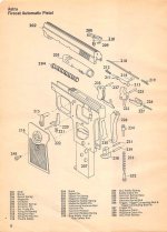
Part #213; shown with the tapered end forward (towards the firing pin), and the slot down.

I tried a long time to put it back as shown in the pic, but just couldn't make it happen. It went together alright having the tapered end towards the back (where it gets hit by the hammer), and the slot facing up towards the top of the slide.

The wear mark on the hammer looks like it had been hitting the smaller tapered end, but I didn't pay close attention during disassembly because I had this pic to go by for putting it back together.
 

Attachments

  • Firecat exp view.jpg
    Firecat exp view.jpg
    239.4 KB · Views: 120
I found one video that shows it and he went through the same thing, and ended up installing it with the tapered end towards the hammer and the slot up.

But, in the comments he states he fired it once and the firing pin broke.

Improper installation, or coincidence and bad luck? Inquiring minds want to know.

https://www.youtube.com/watch?v=gJfZNZSDWC0
 
I'm not familiar with the Firecat, but as someone who at one time in my life did some engineering illustration I find it difficult to accept that whoever drew up that exploded view would have drawn the part upside down and backward. I think the fact that someone installed it other than as drawn and immediately suffered a parts breakage is probably not a coincidence.
 
I understand your viewpoint, but two out of two people (that's all I know about) couldn't get the pieces to go together as illustrated.

There's no way I can see that #214 (firing pin rod pin) is going in when the slot in the firing pin rod (#213) is facing down. I put #214 through its hole in the slide without #213 and looked at it with a flashlight. It looked obvious to me that the slot in #213 must be on top to allow #214 to be installed.

And more times than not, the guys who draw the illustrations aren't the guys who assemble the parts.
 
I assume this is the video you found: https://www.youtube.com/watch?v=gJfZNZSDWC0

I see the problem. It does appear that it can only go in one way, and that's not the way it's drawn. That said, the guy who made the video didn't seem to know what he was doing, so I wouldn't take that video as particularly authoritative without being able to play with one myself to verify that there's only one way to assemble it.
 
That's the same video, and appears to be his first time at reassembly. It's kind hard to watch, but I'm glad it's out there. No editing to make him look wizardly.

I'm almost sure that the parts pic has #213 upside down and backwards. It makes no sense to have the rounded and tapered end contacting the flat end of the firing pin. Those two parts are in a hole where two squared off ends contacting each other would be better, and cheaper to manufacture.

The hammer pivots out of the frame to hit #213, so that's where the rounded and tapered end of #213 should be since the hammer will contact it at a changing angle. That makes more sense than hitting a rod with a square end.

I'll have a chance to shoot it tomorrow (for the first time), and will post the results.
 
I think the breakdown is correct.
The spring slips over the firing pin. All I've ever seen are like this.
I wouldn't think the hammer would be hitting the pointed end of the rod.
 
Three mags worth (18 rounds) and everything worked fine. I stopped early because 10 of the 18 pieces of brass got away.
 
Back
Top