1911 slide stop dimensions

I hope someone out there has better Google-fu than I do. I have encountered a bit of a puzzler:

Cleaning up my (physical) desktop, I unearthed a scrap of paper on which I scribbled some dimensions for the distance the slide stop lug on 1911s projects beyond the out face of the frame (i.e. how far the lug projects into the magazine well). The dimensions I have are:

Unmarked: .197 Standard .45
Number 1: .197 Caliber .45
Number 2: .205-.210 ACE, Conversion Unit, .38 AMU and .38 NM
Number 3: .215-.220 Super .38 & .38 Super Auto [I think this means .38 ACP and .38 Super]
Number 4: . . . . . . . . [nothing typed -- hand scribbled .40 S&W / 10mm ??]
M: . . . . . . .197 Match

So this leads to a couple of questions: First, the copy of the Ordnance Deprt drawings for the M1911 call for this dimension to be 0.201"-.009". .197 is within that range, but is the correct dimension .197" or is it .201 - .009?

Second question: I know Brownells sells slide stops earmarked as being for 9mm. Are those the same as the Number 2 for .38 ACP and .38 Super?

Third question: Is the Number 4 used for .40 S&W and 10mm? If not, what is the Number 4 used for?

Last question: What is the dimension for the Number 4?

Thanks.
 
9mm has a longer catch on the slide stop than a 45 because it is farther to the magazine follower than in a 45 pistol. 38 Super should be the same as 9mm. 40 is in betweem, I suppose, but I haven't measured one. Most manufacturers use the same slide stop for 45 as 40, I just replace them if they cause a problem.
 
Scorch said:
9mm has a longer catch on the slide stop than a 45 because it is farther to the magazine follower than in a 45 pistol. 38 Super should be the same as 9mm. 40 is in betweem, I suppose, but I haven't measured one. Most manufacturers use the same slide stop for 45 as 40, I just replace them if they cause a problem.
And I have had 1911s in .45 ACP that needed a 9mm slide stop to function properly, and I had a 9mm 1911 that worked better with a .45 slide stop.

But that's all anecdotal. I am looking for specific dimensional information to answer the four questions I posed in the opening post.
 
The Kuhnhausen manual has dimensions for the .45 part, at least.
I'd look it up, but we're relocating next week, and everything's packed.
 
0.201"-.009".
Would be the dimension of .201 allowing for a max in tolerance of minus .009. They are allowing minus .000 thru .009 variance.
When reading prints they give you a dimension and +/- or just + or just- and another dimension and that is your tolerance
 
Don P said:
0.201"-.009".
Would be the dimension of .201 allowing for a max in tolerance of minus .009. They are allowing minus .000 thru .009 variance.
When reading prints they give you a dimension and +/- or just + or just- and another dimension and that is your tolerance
I took mechanical drafting and descriptive geometry in high school and college back in the 1960s. I've been doing drafting ever since. I know how tolerances are shown, and how to read them.

But I have some information I wrote down that came from somewhere, and that information is both incomplete and inconsistent. I asked the question because I was hoping to fill in the blank for the .40/10mm slide stop, and resolve the inconsistency in the way the different slide stop dimensions were presented.
 
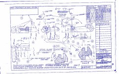
See if the attached Ordnance Department drawing is any help. I have nothing on the non-45 Auto versions.

Don P., you may know this already: Standard practice is to use a unilateral tolerance (+ only or – only) when the given dimension number is critical. The tolerance is then in the non-critical direction. In this case, for the government 1911 in 45 Auto, apparently being longer than 0.198" is a problem, as it could interfere with the operation of some of the guns, depending upon how other tolerances accumulate. The -0.002" value lets it be as short as 0.196", but that will be the fuzzy end of the range owing to it being subject to wear before the next armorer's inspection occurs.
 

Attachments

  • #11 Slide Stop.jpg
    #11 Slide Stop.jpg
    273.3 KB · Views: 27
Unckenick said:
See if the attached Ordnance Department drawing is any help. I have nothing on the non-45 Auto versions.
Thanks. That's an Ordnance Department print I didn't have. This one shows the lug dimension as .198-.002.

I have a reprint of an Ordnance Department drawing revised through 4/19/90 that shows the dimension as .201-.009. I have a reprint of a different version of the same drawing, revised through 10/7/76 that shows the lug dimension as .198-.002.

So somewhere between 1976 and 1990 the gummint revised the specification, tightening up the tolerance range considerably.
 
I would look to see if they changed the magazine follower design during that time. It might explain the shift. Unfortunately, I don't have a drawing for it.
 
I have two sets of reproduced scans from the Ordnance Drawings, one set from Nicolaus Associates, and the other from Western Sky Publishing. They are a mixed bag -- for some drawing the Nicolaus print is newer, for others the Western Sky print is newer. For the magazine follower they are the same date -- revised through 6/21/87. Unfortunately, they don't indicate what was changed from the original. In some cases a revision only reflects that the original drawing was redrawn.

The magazine follower drawing has an original date of 1 May 28, and four revisions.

The width of the follower in that drawing is .472-.006. The same dimension is given in Kuhnhausen, Volume 2.
 
Last edited:
It's too bad the revision actions aren't labeled well. It could also have been a change in tolerance in some place that allowed the longer release tab. I just don't know. You could write the Springfield Armory Museum and ask if they might have some of the earlier prints.
 
Back
Top